
connection informationClick the picture below to view images - Click the right-hand side of the image to view the next picture...
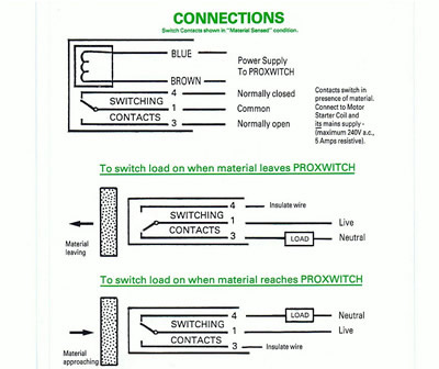
Note: Switch contacts shown below in "material sensed" condition. The Proxwitch connects to the outside world via a 5-core cable.
Two of these wires are exclusively used to power the device. This means that the switching contacts are totally isolated from the supply lines, unlike transistor or thyristor-based designs. Three black cores connect to the changeover relay. These are marked 1, 3 and 4. Use of a tried and tested relay technique means that the Proxwitch is more electrically robust and less susceptible to external damage by the user. All models, regardless of supply voltage can switch up to a maximum of 5A (resistive), 240V AC
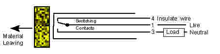
In this example, the load is switched on when material leaves the Proxwitch.
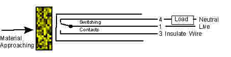
The above diagram shows
connections for switching the load on when the material arrives
at the Proxwitch.
|

© 2013 - Proxwitch proximity switches, G Palmer Electronics, Fareham PO11 3TP UK.- All rights reserved.